What pulse VFD should you be using?
Should you use 6-pulse, 12-pulse, or 18-pulse VFDs?
Explaining pulses in VFDs and what technologies you should consider
Specifications for variable frequency drives are often too complicated. You may feel lost and not understand exactly what is being specified and why that helps you.
We recommend that you write specifications based on performance rather than technology. This allows suppliers to build the system that best fits your needs.
Sometimes you still need to know what a technology is. Our engineers love to explain how VFDs work. One of the questions they get the most is about the difference between a 6-pulse, a 12-pulse, and an 18-pulse drive. Out of those options, which one should you use?
In order to address this, we’ll talk through how a VFD is configured, how each of these methods work, and the best combination of VFD and external technologies to get the performance you need.
VFD Topology
When AC electricity comes in to a VFD, it's first changed to DC. This happens in the “converter” section, named because of the process of converting power. You’ll also hear this section of the VFD called the “front end,” “bridge,” or “input.”
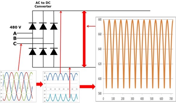
Most 240V and 480V AC power has three phases, called phase A, B, and C. This power is let through the front end of the drive to the DC bus through diodes. A diode acts like a gate or valve. When the voltage exceeds the diode’s threshold, it turns on and conducts. The diagram below shows how this works.
Each phase has two diodes, one for positive and one for negative. This means standard low voltage three phase VFDs are set up with six diodes, which is where the term “6-pulse VFD” term comes from.
Harmonic distortion
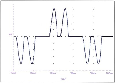
The issue with the standard setup of a 6-pulse VFD is that you chop up the incoming sine wave. This creates harmonic distortion, which is electrical pollution. In a specification, look for terms like THDi, THD, TDD, THVD, and THID when talking about harmonics.
Most 6-pulse inverters create harmonic distortion somewhere around 100%. This waveform looks like the picture below. The goal is to have a waveform as close to a sine wave as possible, which is how you can compare the effectiveness of different harmonic mitigation techniques.
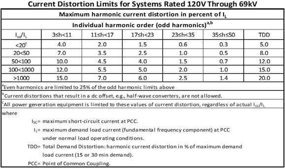
Harmonic distortion levels have limits set by a standard called IEEE 519. Utilities often adopt this standard as the level that your facility needs to meet. The table below shows the distortion limits (TDD) for different size systems.
Adding Pulses
To reduce this distortion, you can add more diode bridges. Doing this gives some harmonic frequencies the opportunity to cancel each other out.
A 12-pulse drive is when you add one more diode set, totaling 12 input diodes. An 18-pulse drive is when you add two more diode bridges, totaling 18 input diodes.
Some manufacturers include all these diode sets within the VFD chassis. Others will sell the extra diode sets separate from the VFD. You then mount them in a panel next to the chassis and wire back into the DC bus.
To make either configuration work, you need to feed the diode sets from a phase-shifting transformer. This is a transformer that shifts the phase angle instead of changing the voltage. A phase-shifting transformer sends a different phase angle to each of the two or three diode sets.
The harmonic frequencies generated by each diode set are different. Some of these frequencies cancel each other out and reduce your harmonic distortion.
12-pulse harmonic improvement
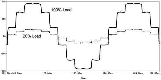
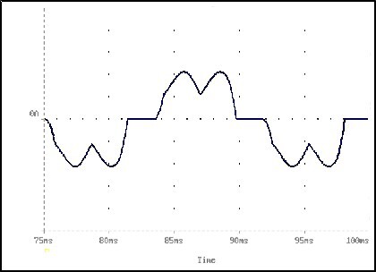
A 12-pulse VFD has some drastic harmonic distortion improvements over a standalone 6-pulse VFD. Compared to the 100% you’ll see with a 6-pulse drive, a 12-pulse will have around 15-20%. Even then, 12-pulse VFDs are not a technology we usually recommend.
Although this technology may meet the needs of some facilities, you can see from the IEEE 519 chart above that 12-pulse VFDs won’t guarantee the performance you need for most facilities.
A 12-pulse VFD carries many of the same costs as an 18-pulse VFD, such as a phase-shifting transformer. At the same time, they provide less mitigation than many technologies, so they tend to be a less popular option.
The waveform below shows a 12-pulse VFD at different load levels.
18-pulse harmonic improvement
An 18-pulse VFD is often advertised as meeting 5% harmonic distortion. We typically see that 18-pulse drives perform closer to the 8-10% mark when measured in the field.
Part of the reason for this discrepancy is that 18-pulse VFDs do better at reducing harmonics when it runs closer to full load and the incoming voltage is balanced. Most systems have a VFD to lower and control the motor speed, so we usually see less than full loads and worse harmonic mitigation performance.
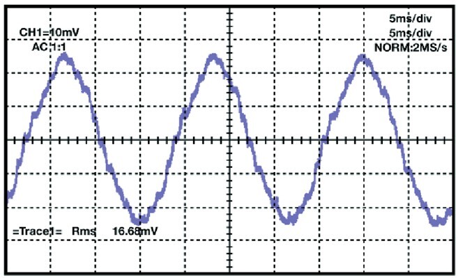
18-pulse waveform
Issues with 12-pulse and 18-pulse VFDs
Although 12-pulse and 18-pulse VFDs are in many specifications, they still have issues. When a manufacturer includes all the diode sets in the VFD chassis, it makes that chassis harder to replace or find. It becomes much more custom and is usually not a stocked item. This means that in case of failure, you’re more likely to see increased downtime and replacement cost.
Phase-shifting transformers can also increase the lead time of a VFD panel. Transformers often have the longest lead time of all components in a VFD panel.
Other Harmonic mitigation options
12-pulse and 18-pulse VFDs are one method to tackle harmonics. These require a more complicated and expensive VFD setup. Using alternative technologies paired with a standard 6-pulse drive is a great way to get similar performance for a lower cost and easier retrofitting in the future.
6-pulse VFD with line reactor
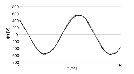
If you’re not concerned with meeting IEEE 519 standards on a particular VFD but still want a dramatic reduction in harmonics, a line reactor may be the way to go. A line reactor adds impedance and will typically reduce your harmonic distortion from 100% down to 30-35%, which results in a waveform that looks like the graph below.
A line reactor is the least expensive option to address harmonics. It also has an added benefit of adding some surge protection to protect your VFD from utility surges and transients.
6-pulse VFD with passive harmonic filter
A passive harmonic filter, also called a hybrid harmonic filter typically sees similar performance to an 18-pulse VFD in the field, with our technicians usually measuring 10-12% distortion. This waveform is shown in the graph below.
A passive harmonic filter is a combination of reactors and capacitors. It is usually cheaper than an 18-pulse VFD and requires fewer custom VFD parts. This system uses a standard 6-pulse VFD, which is easier to repair, replace, and stock in case of issues.

6-pulse VFD with active harmonic filter
6-pulse VFDs can also be paired with an active harmonic filter, or AHF. An AHF acts like noise-cancelling headphones. It reads the harmonics on the system and compensates. This is where the “active” portion of the name comes from.
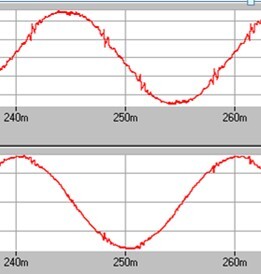
This results in performance closer to 5%. Active harmonic filters are typically modular and can be added to a common bus for VFDs. This gives you options for how to address your entire system's harmonics. You can use a separate AHF to counter harmonics for each VFD system. You can also set up one bank of AHFs to mitigate the harmonics for multiple VFD systems, and even other harmonic-producing devices.
Active harmonic filters are a technology that is growing in popularity. They make it simple to add more harmonic mitigation later, have great performance, and can address other issues like power factor at the same time.
Active harmonic filters result in a waveform like the ones shown below.
Active front end VFD
Active front end (AFE) drives are one of the most expensive technologies to address harmonics. Because of cost, they usually are not used except for in custom or larger low voltage VFD setups, or else in medium voltage.
An active front end is not made of diodes. Instead, the AFE has insulated-gate bipolar transistors, or IGBTs, on the input. Rather than acting like a gate or pressure valve, these function as an electronic switch, opening and closing at high rates.
The VFD tells the IGBTs when they need to open to get the electricity it needs, which means that it is more exact. Where diodes respond to the waveform, the IGBTs are active in managing the incoming power. This is where the active front end name comes from. They may also be called an “active bridge” drive.
AFE drives perform at levels of harmonic distortion below 5%, often from 2-3%. For some applications, harmonics this low and other benefits of an active front end (like regeneration or power factor correction) are worth the cost. For most low voltage applications, the increased performance isn’t worth the price, especially when an active harmonic filter (AHF) can provide similar results for less cost.
Let Us Help You Decide
There are many options to address the harmonics in your system. For most situations, a standard 6-pulse VFD with external harmonic mitigation like a passive or active harmonic filter is the best option. These provide comparable performance to 12-pulse and 18-pulse VFDs, usually at a lower cost.
They also have benefits for the operations and maintenance staff. External harmonic mitigation you have a standard, common 6-pulse VFD that is easy to use, repair, and replace. Stock is typically more available for both parts and the VFD itself. For ease of installation, maintenance, and use, these external devices can still be combined into one panel with the VFD while still being separate components.
These technologies also allow you to add more harmonic mitigation in the future without upgrading the VFD, phase-shifting transformer, or other components.
Reach out for help
How these technologies work can be difficult to understand right away. Our team has worked with all these technologies for years and can help to find what is right for you. Reach out and let our team answer your questions and find the VFD that is right for you.
