High Voltage Spike (dV/dt) and Motor Protection Methods
There are two different phenomena that can create high dV/dt and high peak voltages.
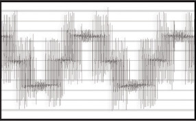
Reflective Wave Phenomenon
Voltage wave reflection is a function of the voltage rise time (dV/dt) and the length of the motor cables. Impedance mismatches cause voltage pulses to be reflected back in the direction from which they arrive. As these reflected waves encounter incoming waves, their values add, causing higher peak voltage. As wire length or carrier frequency increases, the overshoot peak voltage also increases. This causes motor insulation degradation and failure.
Resonant Circuit Phenomenon
Electrical systems of every nature have a natural frequency. When system components have a resonant frequency that matches the natural resonant frequency of the system, peak voltages can quickly exceed standard reflective wave overshoots.
Inverter Duty Motor:
Vrated is the line-to-line voltage
Vpeak is a single amplitude zero-to-peak line-to-line voltage.
For 480V: Recommend voltage spikes be limited to 1000V and dV/dt to 1000V/µs
The definition of what constitutes a “VFD rated” motor varies dramatically. However, one clear difference comes in the rating of the motor insulation. The National Electrical Manufacturer’s Association (NEMA) has two different standards for general purpose motors and VFD motors. Note the difference in the insulation. This is not the peak voltage that the motor can handle during a transient. It is the ability of the motor to handle repeated peaks from the output of a VFD.
For standard motors, we must keep the peak voltage below 1000 volts for a 480V motor. For VFD rated motors, we must keep the peak voltage below 1520 volts. VFD rated motor insulation is rated for 1600V.
dV/dt is also specified. Motor peak voltage AND dV/dt must both be within the specified limits.
Courtesy TCI
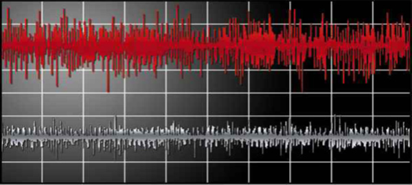
Common mode voltage occurs when the voltages on the three output lines of a drive do not sum instantaneously to zero. dV/dt filters slow down the rate of change of PWM switching as seen by the load. This reduction in the rate of change results in increased capacitive coupling impedance between bearings and bearing races. This increase in impedance, in turn, reduces the damaging Common Mode currents.
Courtesy TCI
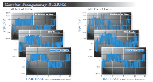
Note that these graphs are at a VFD carrier frequency of 2.5kHz. There are very few spikes above 1000V with 70 feet of cable. The spikes are much worse with 500 feet of cable. Note that these are examples only. A specific application may have no problem with voltage spikes at 450 feet, then have significant problems at 500 feet, and have no problem at 550 feet. The only way to determine whether there is a problem is to measure it. Also, remember that general purpose motors can handle 1000V, while VFD rated motors can handle 1600V.
We do not recommend using line reactors. Our experience shows that they can actually exacerbate the problem in some applications. A dV/dt filter will usually solve the problem.
Courtesy TCI
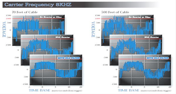
In this example, the carrier frequency has been increased to 8kHz. Note that the higher frequency exacerbates the voltage problem.
High carrier frequencies may also damage dV/dt filters, so make sure you stay within the published limits for that particular filter.
Is there Another Way?
Mitsubishi uses a proprietary motor output algorithm called Mitsubishi Soft PWM and not only reduces motor noise, but also protects from dV/dt. Other manufacturers may or may not have these capabilities.
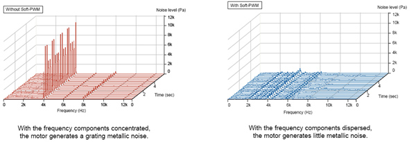
Mitsubishi’s soft PWM algorithm distributes the motor noise over a wider range of frequencies, thus reducing the noise in any one frequency band and resulting in lower dB and a more pleasing sound.
General Recommendations
dV/dt filter
- Reduces voltage spikes to below 1000 Volts
- Slows down PWM dV/dt by a factor of 3
- Reduces common mode currents by approximately 30%
- Protects both the motor and the cable insulation
Recommendations
- Consider when VFD-to-motor cable length exceeds 100 ft
- Option: Leave room in VFD cabinet and install only if required
- Stay within filter manufacturer’s recommendations for carrier frequency
- Use proprietary solution