Motor Buying Guide
There’s likely one motor design that will best meet the needs of your electrical system and mechanics of the driven equipment.
But how do you know which one that is?
A wide range of industry professionals come to us with this question — sometimes with long lists of specification requirements, part numbers or just a description of their application. At VFDs.com, motor users can select units for a wide range of applications across multiple manufacturers, and our experts are here to help custom tailor a solution for them to meet their unique needs.
There are a few things every electric motor customer should consider before making a selection.
You don’t buy a discounted sedan when what you need is a heavy-duty pickup. Yet many people select electric motors based on the lowest price available and don’t think enough about if the motor will meet their long-term needs.
In this guide, we’ll explore the factors to look for in an ideal motor based on the needs of your applications and the realities of your work environment. We’ll help you find the best fit, whether you’re replacing an existing unit or creating a new application.
This article focuses on three-phase AC induction motors. If you have DC or AC synchronous applications, please contact one of our experts. We’d be happy to talk about your application or replacement options.
Application Considerations
This guide will help you gather the necessary information to find the right motor. However, this is just a general overview. If you have technical questions, email us at info@vfds.com, and for the fastest response, give us a call at 1-800-800-2261. We can answer your specific questions and help point you in the right direction.
To get started, we need to know if you’re replacing a motor or starting from scratch.
Adding a new motor
There are some application requirements everyone should know before purchasing an additional motor — horsepower, RPM, frame size, and voltage. These are determined by engineering data from the driven equipment, ambient temperature, altitude, and available electric power constraints.
Replacing a motor
Replacing a motor can be fairly simple. Match the specs on the nameplate and swap in a new one with the same specifications.
That’s fine if the prior unit was a high-efficiency motor that lived a long and happy life. However, if you’re replacing a prematurely failed unit or an older electric motor, some changes may need to be made. You don’t want the new motor to meet the same fate or cost you an arm and a leg on your electric bill.
Key replacement considerations include your budget, suitability for the application, efficiency rating, and lifecycle cost analysis. You may also consider repairing the existing motor depending on the above factors, as well as its stator core and rotor health.
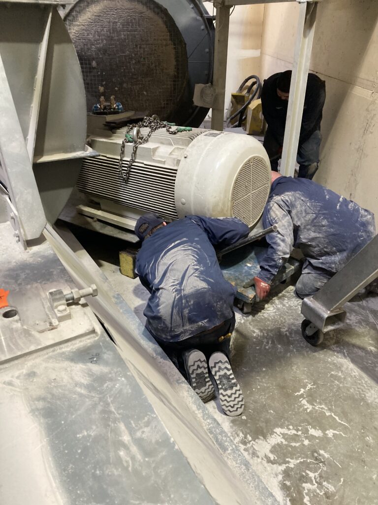
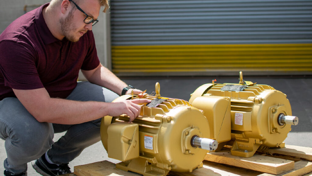
If you aren’t sure, we can help diagnose the issues with your old unit, then find a better replacement or explore repair options. Send our technicians photos of the unit (please send a legible picture of the nameplate), application data, and failure/repair information.
Or if you’re located within our services areas, we can come on site to personally diagnose the problems and recommend the best solutions.
Need a hand now?
We’re here to help with on-site repair and support from one of our service shops in Utah, Colorado, Wyoming, Idaho, Nevada, or California. Give us a call at 1-800-800-2261 to get an expert technician on site ASAP.
The Numbers You Need To Know
Finding the right motor is guided by the demands of your application, whether it’s a simple pump or industrial crusher that is constantly loading and unloading. You need to know what it will take to get the shaft turning, then find the motor that will best operate during the run cycles of the application.
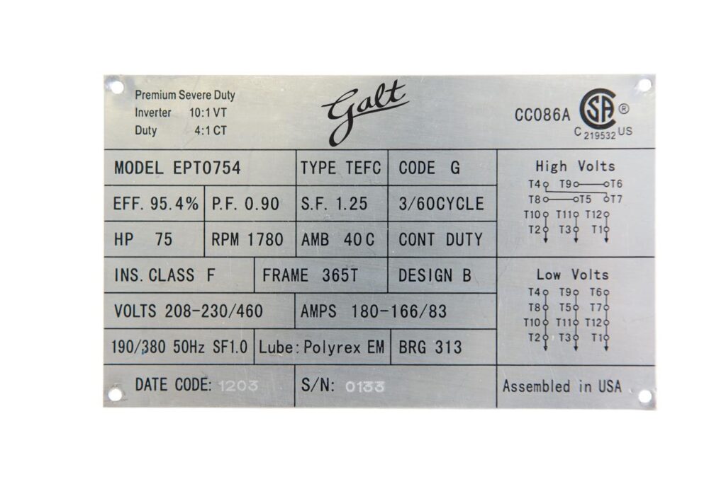
Important motor information is provided on the nameplate, such as its horsepower, speed, voltage, full load amps, and frame size. Other items to consider are efficiency, design type, ambient temperature, and service factor.
Horsepower
Horsepower (HP) or kilowatts (kW) for machines produced for use outside of North America shows how much work a motor can do for you in mechanical output. It is helpful to understand whether you are replacing like-for-like or starting with a new application. If you already know the horsepower of the application you need to run, you will be looking for a motor with an equal or higher HP.
There are multiple formulas you can use if you aren’t sure how much horsepower you need, assuming you do know the speed and torque for your application.
One unit of horsepower is equal to lifting 33,000 pounds of material 1 foot in one minute. Horsepower can be derived from speed and torque (HP = (Torque (ft/lbs) x RPM)/5,250). So let’s say your application needed 1,000-foot pounds of torque and the rotational speed of the application was 1,200 rotations per minute (RPM). In that case, you’d look for a motor close to 228.48HP, which would equate to a nominal size of 250HP.
Quick Tip:
Size your motor conservatively. Applications that require constant torque need more from a motor, especially if you startup with a load (e.g. starting a conveyor belt with products on the belt vs without products). If your motor choice is barely meeting the required spec, consider sizing up.
Speed — RPM
RPM is a speed measurement of electric motors. It refers to the full-load torque delivered at the rated power output and rated frequency.
The speed of the motor is directly related to the frequency of the line voltage and the number of poles in the motor. The measuring unit for frequency is hertz (Hz). In North America, 60 Hz is the standard frequency. In Europe and many Asian countries, the standard is 50 Hz. Common speeds in North America (@60 Hz) include 900, 1200, 1800, and 3600 RPMs. They are also known as 8 pole (900 RPM), 6 pole (1200 RPM), 4 pole (1800 RPM), and 2 pole (3600 RPM).
In an induction motor, there are typically two factors to be aware of — the synchronous speed and slippage. Synchronous speed refers to the rotating speed of the electromagnetic field. Slip is the difference of speed between the synchronous speed and the speed of the rotor. The amount of slip generally increases as the torque design of the motor increases. The speed listed on the nameplate is generally the shaft speed for the motor which is synchronous minus slip speed at full load.
When sizing a motor, you usually refer to the synchronous speed. At 60 Hz, a 4-pole motor will rotate at approximately 1800 RPM (7200/4 poles). However, depending on the amount of rotor slip the motor was designed for, you may see the RPM listed as 1775 or 1750, etc. This number represents what the manufacturer has engineered the motor to rotate at full load with the set frequency listed on the nameplate.
Voltage
Motor voltage is typically determined by the voltage supplied by the utility or plant distribution equipment. If you don’t know the voltage run for your application, you will want to explore what voltages are available for the entire electrical system. Industrial operations will have three-phase power of 208/230V and/or 460V up to 13.8kV.
Most motors should operate within a 10% voltage buffer zone, and we tend to lean towards a 5% tolerance. For example, units designed to run on 230V can typically run at 208V or 240V, though the motor may suffer from heating and larger current draw. A service factor above 1.0 can compensate for some of the difference.
Full Load Amps
The full load amp rating refers to the rate at which a motor will consume power at 100% of its rated load with balanced nameplate voltage. While you won’t necessarily use this to size or choose your new motor, it’s a fundamental figure upon which the wiring, starter, circuit breaker, thermal overloads, and VFDs are sized.

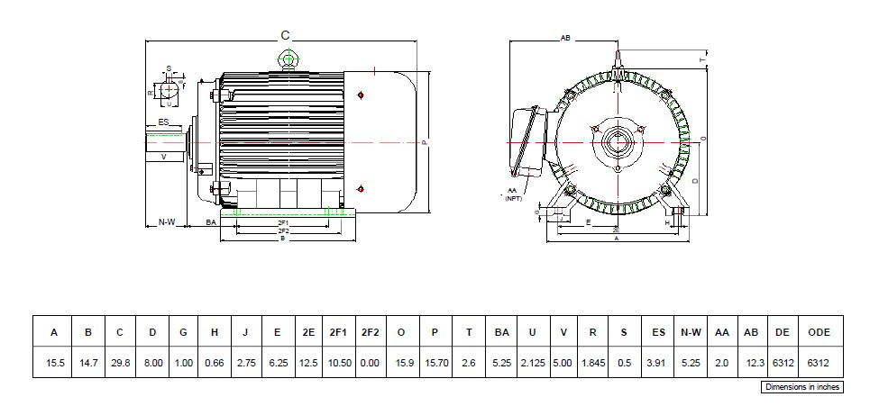
Frame Size
Frame size is a critical aspect to consider since it deals with how you are mounting the motor to your application. The most important dimensions are typically the shaft height and the mounting feet dimensions. But there can be a wide range of motors and mounting types to consider, some standard and others custom. In addition to foot mounts, there are flange mounts, face mounts, special pump coupling mounts, and vertical mounts, among others.
Carefully considering how a motor will fit in your application will pay off during installation.
You can generally expect to see NEMA motors, vertical motors, Above NEMA (ANEMA) motors, and IEC motors, each with varying frame standardization levels.
NEMA Frames
NEMA Frames are sizes seen in regions that use the imperial system of measurement (i.e. feet and inches). They are the most common frame sizes and ratings for the North American market.
Frame size refers to the numbers and letters that represents the motor height, mounting hole dimensions, and the type of frame. The first two numbers divided by four equals the shaft height in inches. This will only give you the height of the motor but not the motor body diameter, because NEMA frame size only refers to the mounting interface of the motor. The third number represents the bolt mounting hole dimensions. There can be different mounting options for the motor.
Vertical Motors
Vertical motors are designed to be directly connected to the equipment. They are capable of withstanding significant thrust, which is why pumps are one of the main vertical motor applications.
There are two types of vertical motors, each solving a different problem in the pump industry. With a hollow shaft (VHS), the pump shaft is connected to the top of the motor through the middle of its hollowed shaft. In contrast, a solid shaft (VSS) typically direct couples to the load.
The sizing of these pumps follows the same principles as horizontal motors.
The main thing to watch out for with vertical motors are the thrust ratings. The depth of the pump shaft can vertically pump water hundreds of feet, creating significant loads on the thrust bearings in the motor.
Above NEMA frames
Above NEMA Frame sizes are bigger than that of the standard NEMA frame list. Usually, they will be 500HP or larger but sometimes have less horsepower depending on how slow the motor runs. These size ranges are not standardized across manufacturers, so pay close attention to the motor dimensions when selecting between different brands.
IEC Frames
IEC frame sizes are typically seen in regions that use the metric system. The numbers of an IEC frame size usually refer to the shaft height in millimeters.
NEMA design type
Design A motors used to be the default for most motor applications. These days, Design B motors are the most popular since they offer a similar starting torque to Design A but with a lower starting current and are a bit more efficient. All this makes them a great option for most applications.
Design C motors have a higher starting torque. They’re typically used for loads that are hard to start and work at a constant speed. This design is great for conveyor belts, compressors, crushers, and positive displacement pumps and blowers.
Design D motors have high slip which results in the highest starting torque and a relatively low starting current. On the other hand, the high slip also means speed is decreased and harder to regulate. This design works well for applications that require significant starting torque or have little speed variability such as oilwell beam pumps, hoists and cranes, punch presses and shears, elevators, and loads with energy storage flywheels.
If you have a VFD controlling the motor, design B will work well for most applications, because the drive allows you to take advantage of higher torque throughout all speed ranges.
Efficiency
Efficiency is how well a motor can take electrical power (its input) and turn that into mechanical power (its output). Basically, how well does your motor perform?
The easiest way to calculate efficiency is to divide the motor’s output by the input.
Manufacturers must guarantee their efficiency to be within a certain tolerance depending on the type of motor design, from NEMA or IEC.
It’s generally a good idea to purchase the most high-efficiency unit you can afford since the initial purchase price usually is a fraction of the lifetime energy savings.
Duty Cycle
Duty or time rating is the length of time a motor can run without a cooling period. This is usually rated in minutes at five, 15, 30, 60, and continuous. Most industrial electric motors are rated for continuous duty. If you happen to have a motor rated for intermittent duty you will quickly run into reliability problems if you run it continuously.
Service Factor
Service factor (SF) ratings indicate a motor’s ability to handle brief demand increases such as loaded start-ups. It is given in a decimal format. If there is nothing listed, the service factor is 1.0. Anything above 1.0 is an additional service factor.
Common ratings include an SF of 1.15 or 1.25. Word to the wise though, exceeding it very often will likely damage your motor. Service factors are designed to give the motor a buffer and not designed for permanent use. Service factor ratings are nice to have and relatively standard, however, you should be aware that most manufactures remove the service factor when running on a variable frequency drive.
Some will use a motor with a designed service factor above 1.0 to occasionally exceed ambient temperatures of 40 C/104 F, high- and low-line voltages, or imbalanced line voltages. If you regularly exceed these levels, you’ll need to consider proper mitigation to keep your motor running reliably for a long time.
Know your specs? Find the best motors
Check out our extensive online inventory of electric motors to meet your needs. Input your HP, and RPM to skip straight to the motors that will best meet your needs.
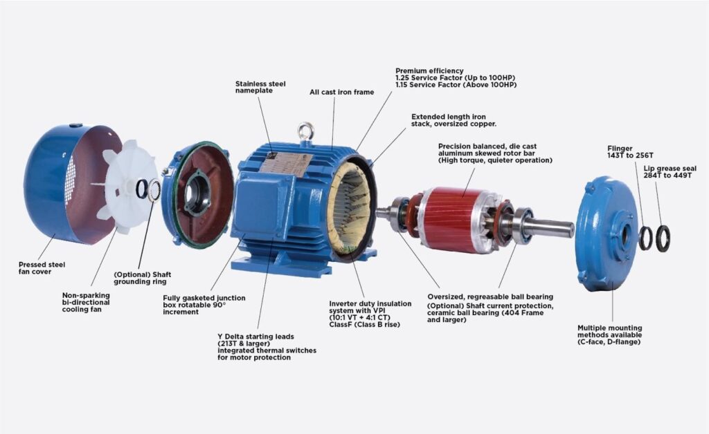
Key Motor Components To Consider
It is unlikely that you’ll need to review every component to get the right motor for your application. But knowing some basics about motor components can give you an edge up.
Electric motors run electricity through coils of wire to create an electromagnetic field. The field develops a rotating force that turns the motor’s rotor and shaft. This creates the torque that allows the motor to power its application, such as running an industrial fan.
The main components we will cover are the stator frame, rotor, bearings, and stator winding and insulation.
Stator Frames: Construction and Enclosure
The outer, stationary part of the motor is called the stator. It includes components like the frame, core steel (laminated electrical steel), and insulated windings.
Enclosures help protect the motor from external contamination and other environmental factors. The enclosure type and construction of the motor can be important parts of ensuring that you have the right setup for your application and environment.
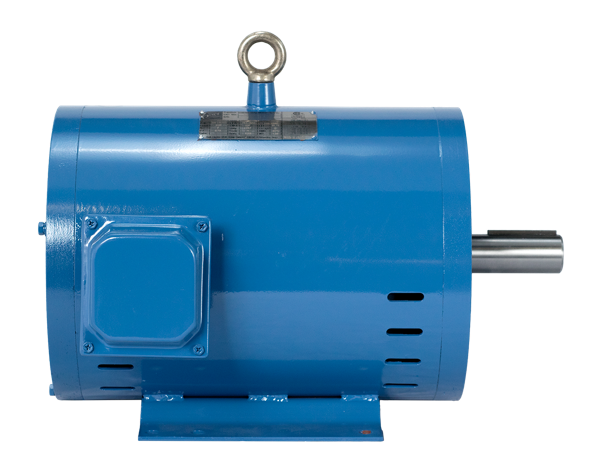
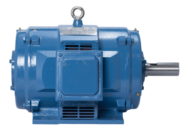
There are many styles of enclosure but the two most common are open drip proof (ODP) and totally enclosed fan ventilated (TEFC). There are many other types of enclosures, including totally enclosed nonventilated (TENV), explosion-proof (XPRF), corrosion resistant, and other fan/blower or water-cooled options.
We can analyze your application and environment to find an enclosure that will protect your motors from all elements at play.
IEC designs do not use the NEMA naming convention for motors. Most will be totally enclosed fan ventilated, but IEC motors are designated by the ingress protection rating system (IP rating). This system gives two numbers designating the enclosure’s ability to withstand particulate and water ingress.
As far as construction goes, we tend to think that the more iron and copper there is in a motor, the better. It helps with motor performance, rigidity, and thermal management.
Rolling steel into a tube is a cost-effective, lightweight way to create a frame, but the strongest heavy-duty motors typically have robust cast-iron frames that are more rigid and durable than their fabricated steel counterparts.
There are different frame constructions to help reduce weight, such as aluminum. These options are becoming more popular in commercial HVAC applications where it can be difficult to lift the motor in tight spaces.
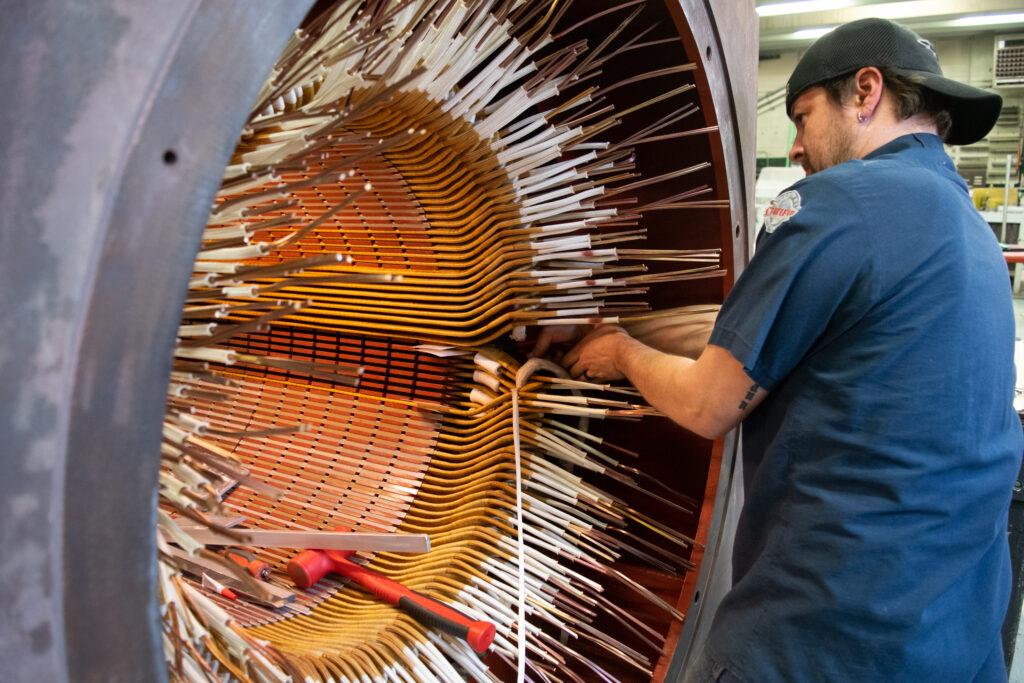
Stator Winding and Insulation
Electric motor insulation is a coating or lamination made of mica, glass fibers, manufactured paper or tape. It is rated for dielectric strength and heat resistance properties. Inadequate insulation is one of the two most common causes of overheating and motor winding failure.
Class F insulation (rated 155 C/311 F) is necessary for motors that operate in high-temperature environments. The next lower tier, Class B (rated 130 C/266 F), has become uncommon as industry demands increase. Class H insulation is the highest rated, maxing out at 180 C/356 F.
When it comes to components like insulation, we recommend getting a bit more than you’ll need rather than risk not having enough. It’s like fishing for 3-pound bass with a 5-pound line — a little overkill won’t hurt.
The life of the winding usually doubles for every 10 C that the winding temperature is reduced or that the insulation system is increased. We recommend Class F for most new motor applications because the upgrade to Class H costs quite a bit more. But if you’re having it rewound, it’s likely worth it to specify Class H, since that’s fairly standard in the repair process.
If you want to go all out to protect your insulation, make sure your motor design includes vacuum pressure impregnation (VPI) or encapsulation.
With a stator that was processed using VPI, the winding is fully submerged in a resin that coats the inner insulation to shield it against harsh environments. The stator is placed in a vessel and sealed, a vacuum is drawn for a time, then the resin is poured into the vessel and into the winding voids. The vacuum is held for another period and then pressure is placed on the top of the resin by compressed air. The resin is driven deeper into the winding, making the core steel, insulation, and wire one solid piece with increased mechanical rigidity and optimal heat transfer.
Rotors
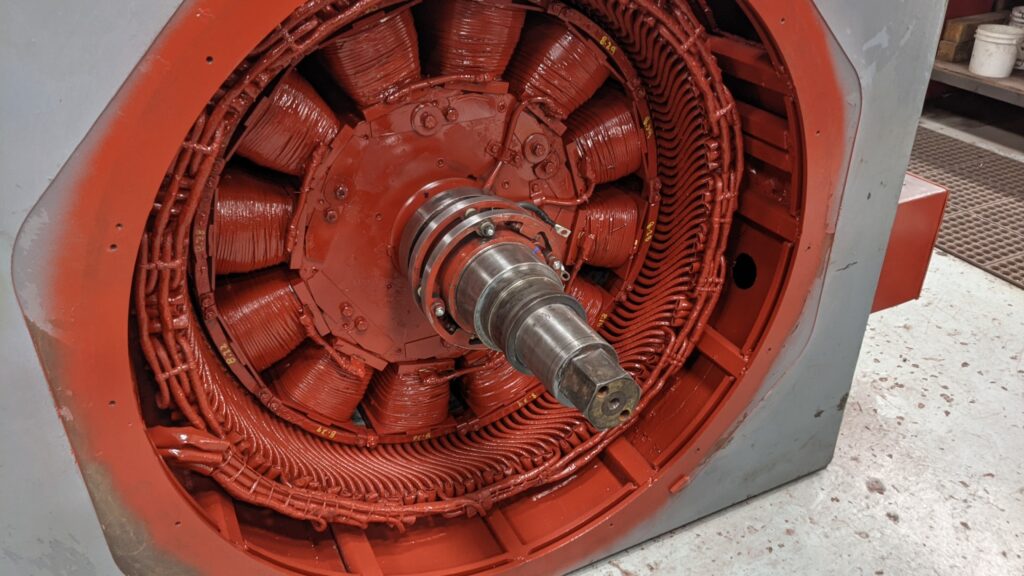
The rotor is the rotating element of the electric motor. Rotor bars conduct electricity by induction from the stator winding to create the magnetic flux that follows the rotating field in the stator. Most low-voltage rotors are aluminum extruded.
We like skewed rotor bars that are designed to increase starting torque while allowing the motor to operate smoother and quieter.
Bearings
The rotor, shaft, and cooling fans are supported by bearings, which bear the weight of the rotor while allowing it to spin. The value of the bearing in an electric motor cannot be overstated since around 80% of electric motor failures are mechanical issues, typically involving the bearings.
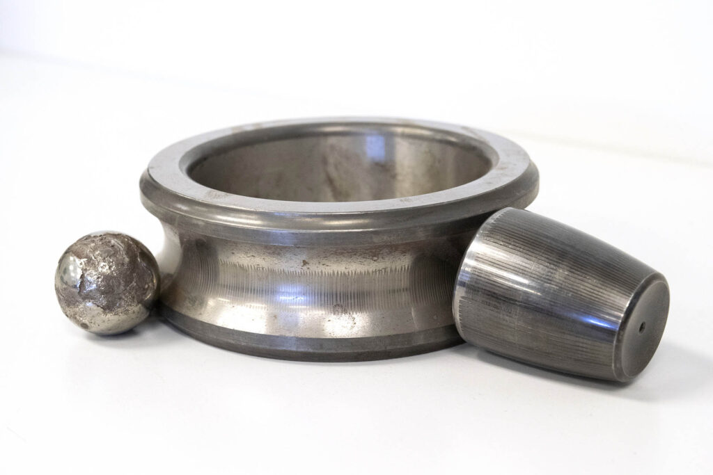
Bearings come in many varieties, such as balls, cylindrical rollers, spherical rollers, anti-friction barrels or hydraulic sleeves/babbitt. You may want to take coupling into consideration when looking at bearing types for your motor. For example, if you’re direct coupled, you won’t want cylindrical roller bearings. However, cylindrical roller bearings can be quite helpful in a belt-driven application to support the radial loads better.
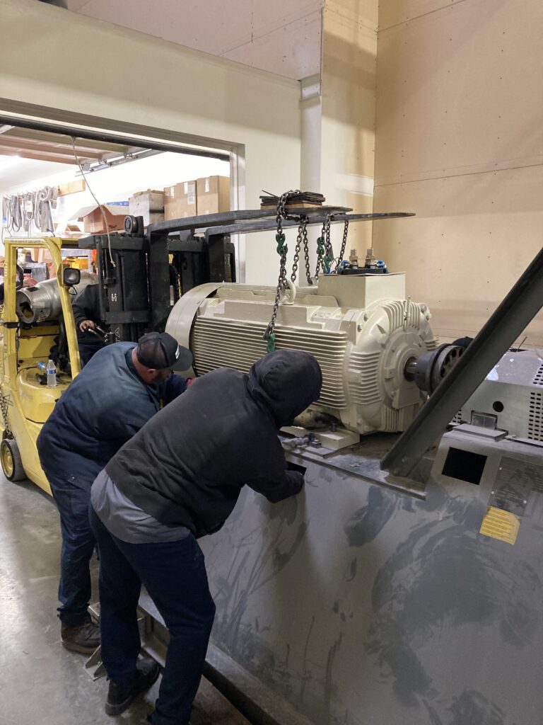
Got to go big?
Do you have a big project that needs a big solution? Get in touch with our expert sales associates to find you the correct motor for the job.
Motor Starting/Control Method
There are many ways to start a motor, each with pros and cons.
It is important to keep starting and control methods in mind when selecting a motor.
When you are replacing or adding a motor in your facility it is also a great time to rethink your control system. It should be no surprise that we are huge fans of using VFDs to start and control a motor. However, there are times when starting across the line or soft starts make sense.
Variable Frequency Drive (VFD)
We recommend considering a VFD for most systems if you don’t have one yet. Adding a drive eliminates motor inrush issues, allows equipment to operate smoother, gives your motor speed control, and could potentially save energy.
For many motor applications, there can be large energy savings potential by operating with a VFD. If you’d like to know if this is a good option for you, we’d be happy to help analyze this with you.

Across the line
The most common and cheapest way to start an electric motor is across the line. Full voltage at line frequency is applied directly to the motor windings, and the motor jolts to full speed as quickly as possible.
It also is the hardest way to start a motor and causes significant mechanical and electrical stresses to your system.
Across the line starters typically use a contactor that applies line voltage to the motor when engaged. This can result in motor starting currents (commonly referred to as inrush) of 6 to 10 times the amount of the motor’s full load amps.
Choosing the correct NEMA design for your application is important when line starting. If you are on a weak electrical system or the motor is a large load on your electrical system, you may notice significant voltage sag that causes your lights or other electrical equipment to dim or flicker.
Your incoming power must be able to keep pace while the motor accelerates. If your electrical equipment design or electricity provider can’t offer enough current, you won’t get the motor to full speed before it trips out or overheats upstream equipment.
Across the line starters make sense for motors that are on a robust system compared to the motor. They also are good for motors that are started infrequently and for applications that always need to run full speed and don’t offer any savings potential at reduced speed.
Soft Start
If your application is always running at full speed, a soft start may offer more energy savings than adding a VFD.
Just like across the line starting, soft starts ultimately run the motor to full speed but do so in a more controlled manner. This was originally accomplished through part winding starts like wye-delta starters. Solid state reduced voltage soft starters (RVSS) have since made that technology obsolete.
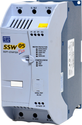
Soft starts significantly reduce the mechanical stresses of starting a motor and brings the inrush current to around 3-6 times the motor full load current. These are great options when you want to reduce the inrush and start the motor softer than the harsh across the line start but do not have any electrical or mechanical advantages for speed control.
Expert help with your VFD issues
Do you need help to get your VFDs up and running efficiently? Technical experts are available to offer step-by-step guidance with installation, setup, and programming.
How Do I Know If My Motor Is Inverter Duty Rated?
One of the most common questions we receive surrounding motors is, “How do I know if my motor is inverter duty rated?”
It is a common issue for good reason. If you are using a VFD to control a motor, it’s important to select a motor that will reliably operate with a VFD.
While there are some standards that help define this, many of the attributes that constitute VFD compatibility are left to each manufacturer. Motors are often marketed as inverter duty rated if they have one or two features, but they may leave you vulnerable to other reliability issues. This is bound to cause confusion as the manufactures jockey verbiage and features to make their models look better than the others.
Don’t forget to consider all aspects of VFD readiness when selecting a motor. This includes wire insulation, cooling, service factor, and bearing protection.
Insulation
Most 230/460V motors are rated for 1000 peak volts. We like to see a better insulation being applied to motors used with VFDs, because VFDs put out pulse width modulation (PWM) waveforms in which the sharp pulses may go over 1000V.
For a 460V system, motors should have wire rated for a minimum of 1426V (nameplate voltage times 3.1 per NEMA MG1 part 31). However, we like to see wire that can handle at least 1600V spikes, F or H class insulation, and insulation that has been processed with resin in a vacuum pressure impregnation (VPI) system.
If you’re running a VFD, play it safe and go with high-spike wire rated for 1600V. It is easy to specify on the front end and much harder to change after the fact.
For 4160V motors, the winding is typically made up of formed coils. In this case, we like to see the rigid coils produced from wire that includes extra insulation before being formed. This is often referred to as double glass over enamel. It means that two layers of fiberglass have been placed on top of the rectangular wire with the enamel coating.
Cooling
Since a VFD can alter the motor speed, it’s important to ensure proper cooling. Many inverter duty motors will designate a turndown ratio to help select a motor appropriate for your expected operating speed range.
For many applications, the motor does not need to operate below 30% of its rated speed and will likely spend a significant portion of time at 50% speed or higher. If this is the case for your application, you probably don’t need to make any special selections, but it would be good to double check that the motor can handle that range or if you should consider auxiliary cooling.
Additional cooling fans can help control internal temperatures. These are crucial for running a motor at very low frequencies/speeds when its fan will not turn fast enough to adequately lower the motor’s internal temperature (See motor cooling in the drive section.)
Service factor
We like to see at least a 1.15 service factor on the motor, even though the motor manufacturer will likely negate the service factor of an electric motor when it is operated with a VFD. It helps to know it can help handle some of the electrical noise that the motor will get from the drive.
Shaft grounding
If you are choosing motors controlled with a VFD, we strongly recommend investing in shaft grounding protection. VFDs can cause millions of little arcs to discharge through the motor bearings to ground every hour. This results in fluting, frosting, and other problems that lead to serious bearing failures.
While there isn’t an absolute solution for these issues, there are a few ways to reduce the damages, such as shaft grounding rings, grounding straps, and insulated bearings and/or housings.
NEMA frame sizes 400 and up should have an insulated bearing on the non-drive end and shaft grounding. When it comes to motors 500HP and larger, you’ll want insulated bearings on the non-drive end and a high current shaft grounding ring.

Motor Environment
Always keep your motor's external environment and internal components clean, cool, and dry to give your motors the best chance of maximum longevity. It might sound like common sense, but this best practice is often neglected.
Moisture
It can take a little extra effort to prepare motors for outdoor or corrosive environments, extreme temperatures, or dust and debris. Even humidity moisture can settle in and compromise stator windings.
Heaters can be installed within the units to keep the components above dew point after shutdown and limit condensation in damp or cold environments.
Temperature
Follow the ambient temperature rating stated on the motor spec when you are considering a new motor.
Think about the operating environment. Whether it is extremely hot or cold, it could affect your choice. Standard North American motors typically are rated at 40 degrees C or 104 degrees F.
Additional cooling fans can help control internal temperatures. These are very important when running a motor at very low frequencies/speeds when its fan will not turn fast enough to lower the motor’s internal temperature. (See motor cooling in the drive section.)
You can also help protect units from within by implementing temperature detectors (see RTDs below) that notify users when a unit is running too hot.
Don’t forget about possible contamination from things like wood dust, fabric dust, metal particles, glass dust, etc. in respective workshops or factories. These particles can accumulate between the motor fins and reduce the motor’s cooling effectiveness. This contamination can trap heat like a parka causing the motor to overheat.
Contamination can also be electrically conductive such as metals or carbon and cause premature failures with a short turn-to-turn, between phases or to ground. Extreme temperature fluctuations can cause the winding’s copper, steel, and iron to contract and expand at different rates, which will wear the insulation at mechanical stress points.
As a rule of thumb, the service lifetime is cut in half for every 10 degrees over the insulation rating that a motor is operated at. In these types of environments, we recommend considering a different enclosure or auxiliary cooling.
Beat the heat
Find the motors, enclosures, and cooling accessories that can withstand hot conditions through long workdays.
Altitude
Altitude is relevant to the motor’s operating temperature as well as airflow density. The rated altitude for a NEMA design motor is 1000 meters or 3300 feet above sea level. You should size your motor according to the altitude of your installation location. NEMA MG-1 specifies that you should de-rate your motor by 3% per every 500 meters (1,640 feet) of altitude gain above 1000 meters (3,280 feet) over sea level.
Hazardous locations
Take extra precaution if you’re working in classified hazardous locations such as the petroleum, water treatment, mining, metal or woodworking industries. Non-spark fans made of brass, bronze, or aluminum or UL listed explosion-proof motors for their specific application can make all the difference in a safe work environment.
Make sure to carefully select the right rating for the motor’s operating environment. There are typically different ratings for operating around explosive particulates vs explosive liquids or gases, whether a flammable substance is normally present or not. Then there are ratings specific to the type of the flammable substance. This information is usually rated by classification, division, and group and is important that you have it correct for the location of the motor. If you aren’t certain, it is best to reach out to an expert to help ensure proper motor selection.
Future Maintenance Considerations
If you’re looking to create a highly reliable and effective system over the long term, some additional components could add to your initial bill but save you a lot of time and money over the years. They are easier to add now than in the future.
Resistance temperature detectors (RTDs)
Resistance temperature detectors (RTDs) can find temperature fluctuations in the windings and/or bearings that could indicate something is wrong.
Windings can overheat when cooling is impeded by dirt or plugged filters. Bearings can also overheat when their lubrication is lost or contaminated, or if they are overloaded. Proper temperature monitoring will alert the maintenance department that corrective action may be necessary to prevent a catastrophic, expensive failure.
Lubrication
You may want to add accessories or extensions for better access to lubrication points to make proper motor maintenance easier.
Vibration sensors
If a minor problem takes place in your motor, you want to know before something else is damaged, especially in sensitive operations.
Vibration sensors can detect issues like imbalance, misalignment or bearing failure so you can react before the breakdown. It could be considered like a check engine light for you motor.
Example Based On Application
Let’s bring it all together in an example case. If we worked with a water municipality to select and configure the best motors and drives for their operation, we would first ask them some basic questions. We need to know about things like:
- Application design (pump) requirements [Pump Curve Example]
- HP/kW
- RPM range
- Voltage
- Frame size requirements
- Mounting considerations
- Pump type
- Coupling method
- Environmental factors
- Ambient temperature
- Moisture
- Particulates
- Altitude
- Indoor/outdoor
- Classification designation requirements for hazardous locations (Class I division 1 or 2 and group type)
- Plans for speed of motor controls (VFD, contractor, PLC, etc.)
- Special installation requirements (mounting, transporting to destination, etc.)
- Necessary attachments (AEGIS rings or monitoring devices)
- Plans for preventative maintenance (greasing, types of bearings used)
- Seasonal or year-round operation
- Warranty length consideration

Browse Top-quality Equipment
Browse our selection of high-quality options after you’ve considered all the demands your application and environment place on a motor. Find the unit and protective equipment that will meet all of your needs for the long term.
Want to make sure you get the perfect fit?
If you’d like some additional advice or support, give us a call and we’ll help you find the best fit for your goals and investments. Our best-in-industry experts have seen it all and know how to get the most out of equipment for any application.