What is PID Control in VFDs?
Many facilities using pumps and fans are constantly fighting the battle of maintaining just the right pressure, flow, or levels in their system. Variable frequency drives are the go-to solution for electric motor speed control because they provide energy efficiency benefits by reducing power consumption according to affinity laws. Another benefit of inverters is that they can help solve this issue for water/wastewater, HVAC, and other industries facing this battle.
One of the most common ways to automate that speed adjustment in these applications is PID control. It’s a headline feature on nearly every major pump drive brochure, but what does it actually do?
What is PID Control?
PID control is a process where VFDs take feedback from a measurement device and adjust the speed of a motor to hit a desired setpoint. PID stands for Proportional-Integral-Derivative, which are all variables that are adjusted within a VFD to achieve this control. VFDs have the logic built in to execute this process. For example, the Mitsubishi F800 manual shows the logic their drive follows.
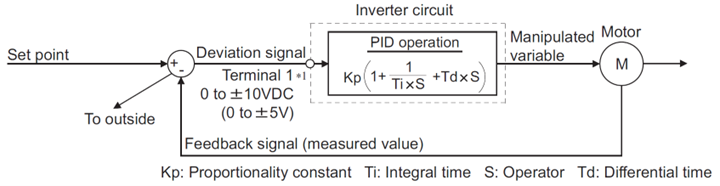
The Mitsubishi F800 PID operation logic loop
If you understood the picture above, then you have a strong grasp of PID control. If your eyes glazed over and you had flashbacks to a math class you barely passed, that’s fine. We’ll break down how PID control works and even relate it to something you’re probably more familiar with. For our example, imagine you’re driving a car and trying to maintain 60mph.
PID – Defining “Proportional”
The “proportional” in PID reacts to the size of the “error” or “deviation” – basically how far off are you from your setpoint right now? If you need to maintain 100 PSI but are seeing 70 PSI, this is the portion that reacts and says you need to increase the pressure, and by how much. In this case, it says that we need to make up 30 PSI. It takes big steps to get close to the setpoint, but rarely overshoots.
When you’re driving a car and trying to maintain 60mph, this is the moment you stop looking at the scenery around and realize that you somehow dropped to 40mph (no wonder everyone was honking at you). Your brain does the quick math and says your daydreaming means you need to make up 20mph.
PID – Defining “Integral”
The “integral” in PID reacts to accumulated error or deviation over time. It asks how long you have been off the setpoint. It’s what reacts to errors over time. Where proportional looks at the amount necessary to get close to the setpoint, integral worries that an error has lasted long enough that we may need to give it a little extra to bridge the gap. It’s a slow measurement that can lead to overshooting because it’s lagging the current status.
From the previous example, you accelerated from 40mph to 58mph, and now your brain says you shouldn’t be flooring it. Over time, you notice that you’re staying at 58mph, but you really want to be going exactly 60. You make the decision to give it a little extra gas to get over that hump and get to the number. At any point in time, you wouldn’t worry about that small difference, but if it’s been that way for the last 10 minutes then you’ll decide to finally act.
PID – Defining “Derivative”
The “derivative” in PID reacts to the rate of change of the error. In most pump and fan systems, derivative is rarely used because the process is slow and stable. For applications with faster rises and falls, the derivative helps to prevent constant oscillation around the setpoint as it often overshoots and undershoots.
As you’re accelerating from 40mph to 60mph, this is the part of your brain that notices we’re approaching 60mph quickly, maybe because we’re going downhill. It’s what worries about the cop that could be parked behind that building on the shoulder and says we don’t want to overcorrect so much that we get a speeding ticket. It’s the brake pedal or the proactive release of the gas pedal to avoid these issues.
PID – Summarized
Now you’ve got the technical background, but what does all that mean in plain English? VFD manufacturers have made it simple for you and included all those considerations into the PID control function. If you don’t need to know all those terms in detail, what’s the one-sentence summary?
PID control looks at the current and trending status of your process to try and keep as close as possible to a setpoint (like pressure, flow, or level)
| Reacts to | What it does (simplified) | |
| Proportional | Instantaneous Error | Big steps to get close to the setpoint |
| Integral | Smaller accumulated error over time | Small steps to close the gap that develops over time |
| Derivative | Rate of change of error (for applications with faster change) |
Smoothing out the oscillations around the setpoint |
Download a version of the above PID control chart here.
What Feedback Devices Are Used with PID Control?
One crucial part of the car analogy is the speedometer. If you didn’t know how fast you were going, all the adjustments would just be guesses. For VFDs using PID control, there are several feedback devices to know about depending on what you want to measure.
Pressure Transducers
Called transducers, pressure transducers, or pressure transmitters, these devices relay back to the VFD what the pressure of a system is. These are usually used with pumps and fans because they measure fluid or air pressure. They are usually sending the VFD a 4-20mA signal, although 0-10VDC is also used – more about that later.
Flow Meters
Flow meters relay back to the VFD how quickly liquid or air is flowing. These are used in pumps and fans where the speed of the flow matters more than the pressure. They are also usually sending the VFD a 4-20mA signal.
Level Sensors
Level sensors relay how full a tank is. These are used with liquid in tanks rather than measuring the work of the pump or fan. There are multiple ways these sensors read, including ultrasonic sensors, pressure sensors, or radar sensors. They send their information to the VFD through a 4-20mA signal.
Temperature Sensors
Temperature sensors are the most unique among PID control feedback devices. They read air, water, or process temperature from a device like a thermistor or resistance temperature detector (RTD) but need a transmitter to convert their readings into a 4-20mA signal for a VFD.
| Application | Feedback Device |
| Pumps and Fans | Pressure Transducer |
| Tanks | Level Senson |
| Air, Water, or Process Head | Temperature Sensor |
Download a version of the chart above sensor chart here.
Why Use PID Control?
This functionality is great, but many motors are currently run by programming a set speed and then letting the VFD run. What’s the advantage of using PID control and adding some initial upfront programming work?
Many facilities are constantly starting and stopping processes to try and maintain certain pressures or levels in their system. PID control means no more babysitting gauges or switches and other issues like:
-
- Electrical stress: Inrush current on motors that run across the line or on soft starters
- Mechanical stress: Bearings, seals, pipes, impellers, and other equipment take repeated torque hits
- Water hammer: The water column reverses and slams back, creating pressure spikes
- Unstable control: Constant undershooting and overshooting of the desired pressure or level
- Warranty risk: Exceeding manufacturer guidelines for starts per hour can void warranties
If you’re just starting and stopping a process manually, you’re likely losing energy. Most applications on PID controls are affected by affinity laws which say that slowing your process down a little bit can save a lot of energy. You can learn more about how that works on our blog post about the Benefits of VFDs, Inverters, and Drives.
Frequently Asked PID Control Questions
We get questions from people using PID control for the first time, but a lot of these questions end up being repeated. Let’s highlight a few of the main ones we get.
How Do I Program PID Control?
Programming a PID control is simpler than you would think. For most VFDs, you only program one parameter: the setpoint. Unless you have an unusual or highly sensitive application, the logic built into the VFD will work great for you. In those cases, there are plenty of parameters to adjust as needed, but they’re often unnecessary.
Then how do you program the setpoint? It’s a little different for every brand and even some series within a brand. Consult your drive’s manual or programming guide for exact instructions.
As an example, let’s look at the Galt G500. You access the parameters (this video shows you how to do that) and go to parameter P09.01. Here you’re going to set a percentage. You calculate this percentage based on the range of your feedback device.
Let’s say you have a 0-200 PSI transducer. Note that for a 4-20mA, that means your range is:
-
- 4mA = 0% = 0 PSI
- 20mA = 100% = 200 PSI
You need to maintain 150 PSI in your system. Divide 150 by 200 and you see that you want your VFD to maintain 75% of the transducer’s measurable range, which corresponds to a 16mA signal. You put “75” into P09.01, and that’s your setpoint.
Why Use 4-20mA Instead of 0-10VDC?
4-20mA is a current signal and 0-10VDC is a voltage signal. Between the two, 4-20mA is the standard for industrial applications. There are a few reasons for this.
Current doesn’t experience as much of a drop as voltage does over long leads. It’s also less affected by electrical resistance and noise. This means you have less concern for long cables between feedback devices and the VFD when you use 4-20mA.
You also have the benefit of having a “live zero.” On 0-10VDC, a signal of zero could mean that it’s no pressure, but it also could mean that you have a broken wire or open sensor. On 4-20mA, these are separate readings: 4mA means no pressure while 0mA means the wire is broken or the sensor is open.
Find the Right VFD with PID Control
PID control isn’t just a feature, it’s what turns a VFD into a smart control system. Whether you’re maintaining pressure, level, or flow, it keeps your process steady while cutting energy use.
Most drives include PID out of the box - we’ll help you choose the right one and show you how to set it up for your exact system. Reach out to our team and let’s make your pumps and fans run smarter.