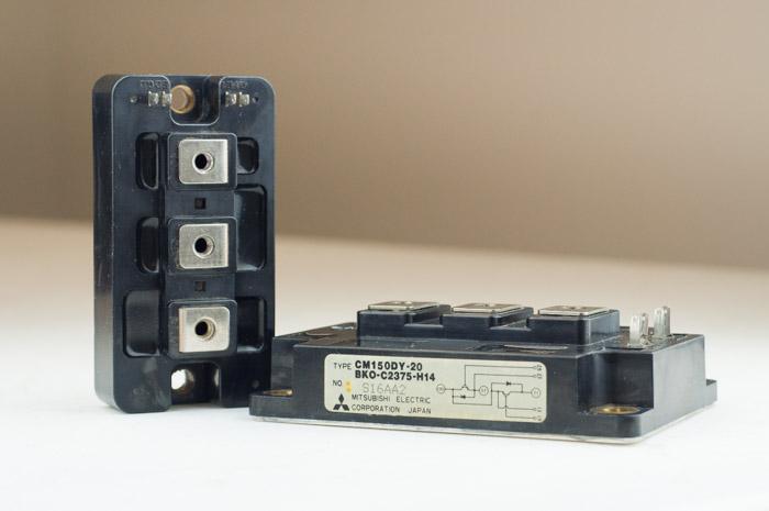
Switching it up: IGBTs
What is IGBT?
An Insulated Gate Bipolar Transistor (IGBT) is a key component in what makes up a VFD (Variable Frequency Drive). If you break down a VFD, one easy way to analyze it is to think of it in three main parts: the bridge converter, DC link, and what we will talk about today, the inverter. An IGBT is the inverter element in a VFD, pulsing voltage faster than we can even blink.
IGBTs have come a long way since they were first developed in the 1980’s. The IGBTs of today are much more advanced than their predecessors, which were slow at switching current on and off and often had problems overheating when passing a high current. With each new generation, IGBTs have continued to improve. No longer plagued by slow speeds, IGBTs have become highly reliable devices that can handle high voltage devices and are able to switch in less than a nanosecond (that’s a billionth of a second)!
IGBTs are the “Gatekeepers” of Current
To understand an IGBT’s role in a VFD, it is important to identify how an IGBT works on a smaller scale. As defined by being a transistor, an IGBT is a semiconductor with three terminals which work as a switch for moving electrical current. Just as the word “gate” suggests, when voltage is applied to the gate, it opens or “turns on” and creates a path for current to flow between the layers. If no voltage is applied to the gate, or if the voltage is not high enough, the gate remains closed and there will be no flow of electricity. In this way, an IGBT behaves like a switch; on when the gate is open and flowing current and off when it is closed.

In this way, the IGBT acts as the switch used to create Pulse-Width Modulation (PWM). An IGBT will switch the current on and off so rapidly that less voltage will be channeled to the motor, helping to create the PWM wave. For example, although the input voltage may in reality be 650V, the motor perceives it as more like 480V by using PWM (shown in diagrams below). This PWM wave is key to a VFDs operation because it is the variable voltage and frequency created by the PWM wave that will allow a VFD to control the speed of the motor. Therefore, without the IGBT switching the current on and off so rapidly a PWM wave—and the speed control that comes with it— could not be created.

480V 60Hz

80V 10Hz
The number of pulses per second from the IGBTs is known as carrier frequency. Since carrier frequency is an adjustable parameter on most VFDs, you can essentially set it as high or as low as you want. Although, adjusting the carrier frequency comes with a few tradeoffs. Setting the carrier frequency too high will reduce the acoustic noise level produced from the VFD, but it will also shorten the expected VFD life due to heat. A higher carrier frequency will also contribute to an increase in motor heating and affect the overall efficiency of the motor. On the other hand, if you are in a sound sensitive environment – or if you just don’t want a headache – setting the carrier frequency too low can create a lot of motor noise or whining from the VFD. We have found that setting your carrier frequency at about 2 Kilohertz will achieve a nice balance between the audible acoustics while still keeping your VFD running efficiently.
In a typical six pulse drive there are six IGBTs pulsing voltage up to 15,000 times per second. Since their introduction in the 1980’s, IGBTs have literally switched up the market and now play a large role in many modern day power electronics applications where speed and process control are needed. It is clear that IGBTs play a large role in many power electronic applications and will continue to as they become more and more advanced in their technology. Hopefully taking this in depth look at the small part an IGBT plays has helped you to understand the overall functionality of a VFD as well.
Check out our other featured articles for everything you need to know about VFDs and motors at in the VFDs.com Learning Center, or click on the banner below to find the VFD you are looking for out of our 2,000+ inventory!

