Guide to VFDs for Commercial Electricians
Electricians power the world but often don’t have much experience with motor controls like variable frequency drives (VFDs). They encounter motor controls in a variety of industries and applications, but most commonly in HVAC and pumping situations.
These products are often bought through the mechanical scope of a bid project as they are built into HVAC units or pumping skids but are required to be installed by an electrical contractor, adding to confusion. This also means they may have been undersized or might not have the appropriate overload or service factor.
This guide is meant to help electricians tackle the actual issues and questions they have on job sites where they encounter VFDs. It will cover high levels of a few topics like how a VFD works and what power quality issues it introduces, as well as making sure that the VFD is sized correctly and compatible with the motor. It will then dive deeper into the aspects electricians deal with every day, including installing, programming, and troubleshooting VFDs and related problems.
Need quick help? Jump to the relevant section below:
How a VFD Works - And Why It's Different Than Utility Power
Becoming a VFD First Responder
How a VFD works - And Why It's Different Than Utility Power
The most important part of a VFD to an electrician will be the terminals or lugs where power is connected. Incoming power is connected to incoming lines, with the three phase lugs often being labeled R, S, and T. This power feeds to the converter, which takes the sinusoidal AC waveform and converts it to DC. It goes through some internal components, such as the DC bus and attached DC capacitors, then is inverted back to a fake sine wave through the inverter, which is where VFDs earn the nickname "inverter". The power then leaves the VFD through the output terminals, often labeled U, V, and W.
Without getting into too much detail about how a VFD works, it is important to know that for most low voltage (under 1000 V) VFDs, the converter is made of diodes and the inverter is made of IGBTs, or insulated-gate bipolar transistors. Why is that important? Let’s start on the outgoing side.
Pulse Width Modulation, or Fake AC
Many motor issues are more understandable when you learn that a VFD doesn’t actually output an AC sinewave, but it creates a simulated sinewave by sending out pulses of DC power at varying frequencies. By sending positive DC in an increasing and then decreasing frequency, then switching and sending negative DC in the same way, it creates a wave that looks like an AC sinewave if you squint hard enough. Luckily motors are like the dumb work animals of industry and think this fake sinewave is good enough to magnetize the motor and spin. This works because they're an inductive mode, but this sinewave wouldn't work on most other devices.
This output process is called Pulse Width Modulation, or PWM, and causes some side issues like common mode, dV/dt, and bearing damage in the motor. These are more complicated issues, but just know that they can lead to motor damage, especially in the bearings or the first turn of the motor winding.
It’s also important to know that you can change how many pulses the VFD is sending out. This is called the carrier frequency, and it’s typically best to avoid messing with this unless you’re seeing issues. Increasing the carrier frequency means the IGBTs turn on and off more often, which can help to reduce audible noise and make the output look more like a clean sinewave, causing less bearing damage. The downside is that this increases the heat in the VFD, can lead to premature failures, and may even require that you upsize the VFD. Check your specific VFD’s manual, but typically VFDs can operate in a range of 2 kHz up to 4 kHz, although some can go higher.
The Number One Electrical Polluter
On the input side, the diode front end is simple but leads to power quality issues. VFDs cause harmonic distortion. This is basically electrical noise at a multiple of the base frequency. Within a 60 Hz system, the third harmonic is at 180 Hz, the fifth is at 300 Hz, and so on. For three-phase systems, the third harmonic is cancelled out within the system, and your worst distortion is at the fifth harmonic. This is well explained by Power Quality Components in their post covering harmonics. These harmonics can cause issues or damage throughout a facility and can also draw negative attention (like potential fines or shutdowns) from the utility. They’re not always easy to detect and solve, so if you suspect power quality issues, pull in an expert.
VFD System Components
VFDs can be installed as a chassis unit directly onto the wall, DIN rail, Unistrut, or even floor mounted. They also can be built into an enclosure with other components. Below we’ll give a list of some components you may see in a VFD panel and what they’re used for. An example panel can be seen in this article, including pictures of different components.
| Styles | Purpose | |
| Bypass | Electronic, 2-contactor, 3-contactor | Allow motor to run at full speed in case of VFD failure |
| Harmonic Filtering | Reactor, passive filter, active filter, active front end, 12- or 18- pulse converter |
Reduce harmonic distortion from the VFD either by changing VFD function or cleaning the power |
| Output Filtering | Reactor, dV/dt filter, sinewave filter | Improve PWM waveform from VFD output to protect the motor |
| Controls | Human Machine Interface (HMI) screen, keypad, control power transformer (CPT) |
Allow communication of conditions and control from operators |
| Surge Protection | Surge protective device (SPD), lightning arrestor | Protect drive and components from surges |
Motor and VFD Compatibility
Most electricians are not the person who sized and sourced a VFD, but being able to verify compatibility is an important first step in the commissioning and troubleshooting of a VFD. You can read a more in-depth guide to sizing a VFD here, but this high-level view can help you at least catch the biggest issues you’ll run into.
VFD Sizing
A VFD needs to be rated at least as high as the motor’s full load amps, or FLA. Check the nameplate on both, and typically you want a little bit of buffer between the two ratings. Check if the VFD mentions an overload. There may be duty terms like light, normal, or heavy, but these don’t have industry-wide standards. Look for a percentage, typically over 60 seconds. As a general rule, light applications like fans and centrifugal pumps need a smaller overload like 110% or 120%, while heavier duty applications like conveyors and compressors need more overload, such as 150% or 200%. For more details on sizing a VFD, check out our VFD Buying Guide.
Motor Construction
Because of the PWM waveform from the VFD, motors should be classified as “Inverter Duty” to improve long term reliability and avoid failures. Look for that term somewhere on the motor nameplate. Look for insulation that is a minimum of class F, although class H and other higher insulation classes are better. In general, this level of insulation can handle the occasional spike that a VFD may send. You can read our article "How to Read a Motor Nameplate" to learn where to find this data.
Also look to see whether it mentions having insulated bearings or a shaft grounding ring (SGR) installed. Both of these will help to avoid the damage from electric discharge machining (EDM) that comes from VFD outputs.
One important note is that when you run a motor on a VFD, you lose the service factor. Even if the motor nameplate says it has a service factor (SF) of 1.15, 1.25, or any other number, when a VFD is used to control the motor you should consider it to now have a service factor of 1.0.
Check the Motor Minimum Speed
Many motors, like totally enclosed fan cooled (TEFC) style motors, are cooled by a fan attached to the shaft and spinning at the same speed as the motor, pushing air over the outside of the motor and through cooling fins. It’s counterintuitive, but in these cases, slowing down your motor can increase the heat. The fan loses cooling efficiency faster than the motor loses heat generation, so these motors can be prone to overheating at slower speeds. If the motor runs below 50% of its rated speed you may want to investigate this issue, and anything below 25% should be a red flag to talk to an expert or look into alternative cooling methods like blowers.
Installing VFDs
Before getting into any suggestions or general guidelines, it’s important to note that nothing we say should override code or manufacturer requirements. Before doing anything, make sure to check your local electrical code, the VFD manual, and the specifications and plans for your particular job. Always make sure that safety is the first consideration in your work.
With that in mind, there are still often some general questions that we get asked by electricians. We’ll go through these topic-by-topic so that you can skip to the information you need. For basic wiring, the Galt Electric wiring guide shown below is helpful as an example of the right way to install a VFD. We also created a video using a Mitsubishi as an example of how to wire a VFD. Also know that when a VFD is being used for phase conversion, the input wiring will be different.
Galt Electric Wiring Guide Video:
Grounding, Bonding, and Shielded Cables
Grounding and bonding are crucial for VFDs to avoid the high-frequency electrical issues that can come from a VFD, including nuisance trips, motor damage, and interference with other equipment. In general, you will follow the electrical code with only a few minor clarifications.
First is that you should not be using conduit as your only ground. You need to ensure both mechanical and electrical grounding and bonding, so run a full-sized equipment grounding conductor from the utility ground to the VFD chassis or panel.
Bonding the motor frame properly is also crucial. Terminate the equipment ground to the motor ground lug. Scrape paint if needed and ensure tight metal-to-metal contact. Loose motor grounding can be a major cause of both nuisance ground fault trips and bearing damage. If there’s any mention from the customer of bearing damage, shaft grounding rings are cheap insurance against EDM.
In systems 600 V and under, shielded power cable is generally not required, but most VFD manufacturers will recommend using concentrically grounded cable to reduce EMF. Start and stop signals are fine to go through standard wire, but all analog signals and 4-20 mA loops should utilize shielded wire.
Wires should be terminated 360° at the drive end with a proper lug. Pigtails are less effective at high frequency, so avoid those. Low voltage control wiring or analog signals should be separated from motor leads. Cross the power wiring and control wiring at 90° if they have to intersect.
Motor Lead Length (dV/dt)
Although some manufacturers will say figures like 300 or 500 feet, our dV/dt rule of thumb is that you should worry about dV/dt and winding damage whenever the cable from the VFD to the motor is over 100 feet or cables are submerged in water. We mention this concern with EDM and bearings, but long motor lead lengths can also affect the winding.
Common methods to address this include reactors, dV/dt filters, and sine wave filters. Our testing has shown that a 5% output reactor is just as effective at filtering a VFD output as a dV/dt filter for almost all applications, but typically at a lower cost.
With those results, our general rule of thumb is that an output or load reactor should be used in situations with a lead length between VFD and motor under 1000 feet while a sinewave filter should be used on any lead lengths over 1000 feet or any submerged motors or cables. These filters need to be installed between the VFD output and the motor. You can learn more about this issue from Power Quality Components' article "What to Know About dV/dt and Reflective Wave Phenomena".
Breaker and Wire Sizing
Breaker and fuse sizing should follow the electrical code. Breakers should be sized as you would any other electrical system. As with many other applications, the wire needs to be 125% of the load rating as a minimum. With VFDs, we often recommend 125% of the VFD rating (rather than the motor) as the minimum in case motors are replaced in the future and more of the VFD capability is utilized.
Disconnects
Although it can vary, code typically requires a disconnect to the VFD within 50 feet and within line of sight on the input side of the VFD. In some situations, such as when a VFD is built into an HVAC unit or air handler, there is a breaker with LOTO capability built into the unit that may work. If there is not, we often see a requirement to install a disconnect near the VFD.
On the output side of the VFD, a disconnect is often placed between the VFD and the motor to function as a motor isolation switch, allowing LOTO work on the motor. This is typically in the form of a fused or non-fused knife switch. These come with an option for a make-before-break contact with the knife switch that will send a signal to the VFD that the motor is being isolated.
This signal is often wired into a VFD in one of two ways. First is that you can bring it into the STO (safe torque off) or safety switch terminals. This often includes bringing into one terminal and placing a jumper on other terminals. On a Galt G500 for example, you would connect to +24V and either H1 or H2 and jumper H1 and H2 together.
You can also connect to a digital input for remote e-stop functionality. In the case of a Galt G500, you could utilize the S4 terminal as an example.
Clearance and Cooling
One of the most common causes of failure on a VFD is heat. When installing drives, proper cooling may require them to be installed with only certain directions facing up and with certain clearance on the top, bottom, back, or sides. This will typically be in the VFD manual in the installation or dimensions section. Make sure to get an enclosure that provides the right protection while allowing as much (clean) airflow as possible. Learn more in our article about the enclosure rating systems drives use.
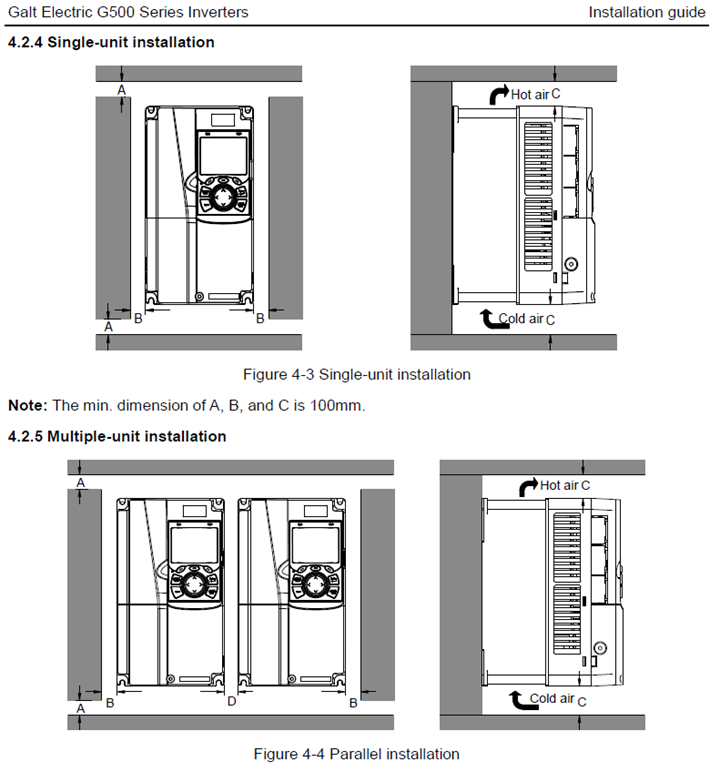
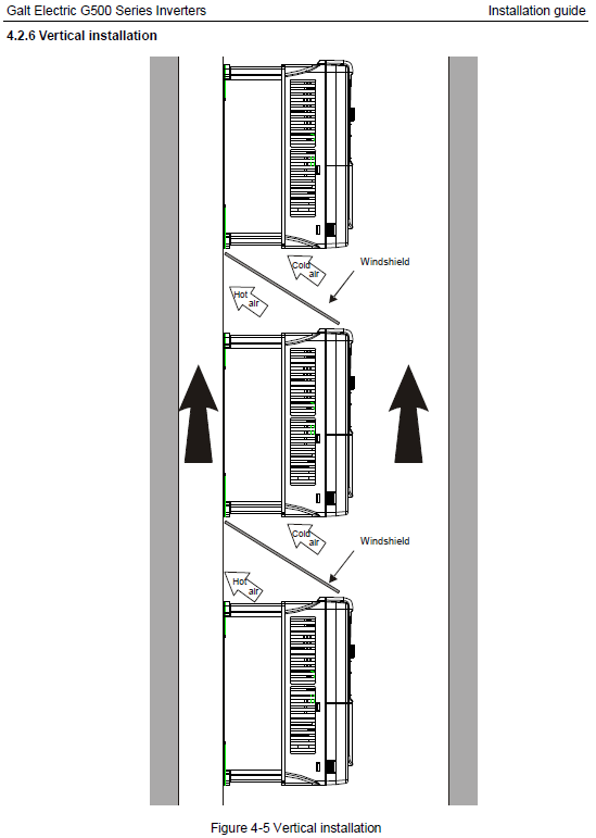
Example installation guidance for the Galt G500 VFD
Basic VFD Programming - The Three Parameter Groups that Make Your Life Easier
Most electricians will never need to be expert VFD programmers or need to know parameter lists like the back of their hand. What they can know is the general name of several important parameter groups that can help them get 95% of VFDs off the ground and running. We have a few specific guides for VFD programming, such as our basic guide as well as a video guide from Galt Electric showing how to use a keypad to program a G500. We also created an example video for programming the Mitsubishi D700 as another reference, as well as several other lines on our learning center.
Many drives will come with a quick start guide (like this Galt G500 brochure) or other literature to help with basic information. These tend to be quick ways to find basic parameters or control circuit diagrams. If that’s not available, the manual will have all the required in-depth information.
Galt G500 Programming Parameters:
Basic Parameters
These parameters give basic information for running the motor. Taking a Galt G500 as an example, these are grouped under the “P00” parameter group. Look for parameters that cover:
- Minimum and maximum run speed (typically in Hz)
- Acceleration and deceleration time (typically in seconds)
Start/Stop Parameters
These parameters cover some basic styles of starting and stopping the motor. In the Galt G500, these are grouped under the “P01” parameter group. Specifically look for:
- Start mode or “catch-a-spinning-load” - Whether the VFD can begin to run a motor that is still spinning
- Stop mode or “coast to stop” - Whether the VFD allows the motor to either naturally slow (coast to stop) or tries to slow within a certain time frame (decelerate)
Motor Parameters
These parameters tell the VFD about the motor so it knows how to control and protect it. The Galt G500 has these under the “P02” parameter group. Look for:
- Rated power (often in kW not HP)
- Rated frequency (in Hz)
- Rated speed (in RPM)
- Rated voltage (in Volts)
- Rated current (in Amps)
Other Parameters
There are many other parameters that you can adjust. Most manufacturers have hundreds of parameters for niche needs, but many are preset in a way that you won’t ever need to change them because the defaults work for most common applications. Most other times you may need to adjust parameters because of external devices and configuring inputs or outputs like 4-20 mA signals, PID loops, or 0-10 VDC signals. If you’re unsure how to deal with these and you need to configure any of these types of input or output, consult the manual or an expert.
Becoming a VFD First Responder
As soon as there’s an electrical issue, a call goes out to an electrician. If that electrician isn’t familiar with VFDs and finds the issue may be related to a drive, there’s a decent chance they can fix most common issues with just a little background knowledge. If it’s more complicated, there’s still information they need when they call a VFD expert that makes everything go smoother. We’ll go through the most common problems we get asked about, what causes them, and either some likely fixes or what you need to determine before calling a drive expert.
First Checks
It may seem simple, but taking a moment to assess the situation and gather basic information is often a step that gets skipped. Avoid hitting reset and letting the VFD and motor run just to “see what happens.”
Start by evaluating the environment and seeing if anything looks immediately out of place, especially looking for issues with excessive heat, vibration, or moisture. Check the motor wiring and nameplate, the VFD nameplate, and do basic electrical tests, such as on the incoming voltage.
Look at the VFD keypad or screen. If there is a VFD fault present, get the name of that fault. Each manufacturer does this differently. Some will name the fault after a description of what is happening, such as “IOC” meaning “Instantaneous Overcurrent.” Other brands will give you a number or code that you need to look up in the manual. If possible, hit a button to go a level deeper and scroll through the information to determine the frequency, current, and voltage at the time of the fault.
Occasionally you’ll see a minor fault, often called an alarm, that gives you information about potential issues but doesn’t stop the process. These are still important as they give you the chance to solve an issue before it becomes serious.
To see an example of how to check faults, the Galt Electric basic troubleshooting video below can be helpful.
Galt Electric Troubleshooting Video:
Weak Utility Feeds and Generators
In some cases, you’re seeing an issue not because of anything at the facility, but because there’s a weak utility feed or a generator feeding this system. In many of these cases, a large VFD can act like an elephant drinking at a pond – it’s a big user that disrupts the system and causes problems like sags, voltage drop, and flat topping.
Many VFDs are installed to help eliminate inrush current and solve this problem, but the issue may persist. If that’s the situation, you’ll be looking at a more in-depth technical fix, such as changing how the motor starts, looking at the power you get, or other larger fixes.
Phase Imbalance and Loss of Phase
If one leg of the power is weak compared to the others, you have a phase imbalance. This issue is rare in low voltage systems. If you have completely lost a leg of power, then you have a loss of phase. This can be on either the input or the output side. To solve this issue, look for blown fuses or damaged wires as the most likely culprits.
Overvoltage
Overvoltage faults mean that there is too much voltage on the DC bus in the VFD. VFDs have some built in wiggle room (typically 10-15%), but bigger variations will cause an issue. This can come from either the input or the output of the drive.
On the input side, you may have high voltage from the utility, such as the utility supplying 520V on a 480V system. On the output side, you may have regeneration coming from the motor or application. This could be solved by lengthening the deceleration time in the parameters or by adding a place for that energy to go, such as a braking resistor or enabling a coast to stop parameter to allow the VFD to let go of the load.
Know that everything could look like it’s within tolerance, but you still have a problem. This is often because you could have smaller problems on both sides. The utility may start supplying 500V, which is within the capability of the drive, but you also have some slight regeneration. Together these issues put too much voltage on the DC bus, although one on its own isn’t a problem.
Undervoltage
This fault is the opposite of overvoltage. The DC bus has too little voltage, and again it comes from either the input/line side or the output/load side. In this case, however, you’ll likely find that over 90% of the problems come from the line side where low voltage is being supplied. On the output side, you may sometimes find that large starts require the VFD to send too much current too quickly to the motor, dropping the DC bus voltage. In those cases, adjusting the acceleration ramp will often be your first step.
Overcurrent and Overload
Overcurrent and overload are similar faults but should be treated differently. Both mean that the motor is pulling too many amps from the VFD. For an overload, it is a smaller overage over a more extended time, where an overcurrent is a higher instantaneous amount.
Overloads are most often based on small changes in the motor, driven equipment, or load. Something has started to work harder than it should, whether the driven equipment is being overloaded, bearings aren’t spinning as easily as they should, or other issues that build up. Determining which caused the issue, or if it was the sum of all parts, can be tricky.
Overcurrents are typically a more serious issue. You may need to look for short circuits, seized loads in the driven equipment, or completely failed bearings. One quick check is to see if the motor shaft still spins freely when uncoupled.
Although a manufacturer gives overload ratings at intervals like 60 seconds, 10 seconds, or 3 seconds, the determination by a drive to go to overload or overcurrent is based on an overload curve. If the load is consistently sending the drive into a fault, you will likely need to start with an amp clamp to determine what the current from the VFD to the motor looks like.
Ground Fault
A ground fault is when the VFD is sending out current, but that current doesn’t return at the same level. This means that somehow current is going to ground somewhere else, and identifying where that is happening is the first step to solving this issue.
Breakers and Fuses Tripping
We often get calls that a VFD is causing breakers to trip and fuses to blow in a facility. While this may be the case, it’s important to note that there’s no unique reason why this would be happening due to a VFD compared to any other equipment. There are two likely causes of these issues.
First is that there is a short circuit somewhere that needs to be found and fixed. Second is that the breaker was undersized, often because upgrades were made to a system, like adding a motor and VFD, without evaluating breaker sizing. Check breaker sizing in these cases and make sure it’s still appropriate.
If your VFD is being bypassed, you may find that the lack of a VFD is causing tripping. Because of the inrush current of motors started across the line or on bypass, breakers sized appropriately for a VFD may trip when a motor starts without one. This may be helped with a Motor Circuit Protector (MCP) breaker, a magnetic breaker that can be adjusted to allow inrush when a motor starts.
Get Some Help
There are plenty of cases where it makes sense to get help from someone who works with VFDs every day, whether for sizing, installation, or troubleshooting. Even with these cases, we often find that the information in this article is enough to help solve most common issues and help make the electrician the hero who saved the day. When they need to call in backup, having completed some of this work and equipped with this knowledge, the process goes faster and easier for everyone.
Still have questions? Reach out to our experts at VFDs.com here, or call us at 1-800-800-2261 to get support on your drives today.